
2000 Victory V92C Maintenance Guide
Periodic Maintenance Chart


Spark Plug

Engine Oil Level
Engine Oil and Oil Filter Replacement


Air Filter
Brake System


Clutch Adjustment

Lubrication Points

Sidestand Pivot

Front Fork Inspection

Fuse Replacement

Headlight Adjustment

Drive Belt Inspection

Spring Pre-Load Adjustment

Rear Wheel Alignment Inspection & Adjustment

Battery


LCD display function

Troubleshooting


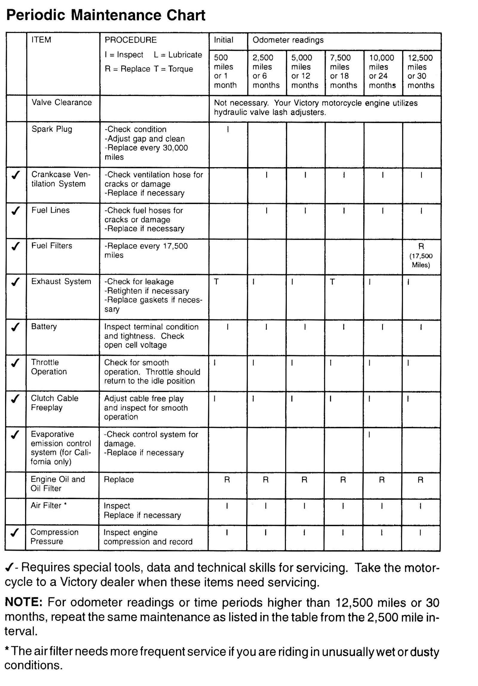
Periodic Maintenance ChartITEMPROCEDUREInitialOdometer readingsI= Inspect L = Lubricate R = Replace T = Torque500miles or 1 month2,500miles or6 months5,000miles or 12 months7,500miles or 18 months10,000miles or24 months12,500miles or30 monthsValve ClearanceNot necessary. Your Victory motorcycle engine utilizes hydraulic valve lash adjusters.Spark Plug-Check condition-Adjust gap and clean-Replace every 30,000milesICrankcase Ven-tilation System-Check ventilation hose forcracks or damage-Replace if necessaryIIIIIFuel Lines-Check fuel hoses forcracks or damage-Replace if necessaryIIIIIFuel Filters-Replace every 17,500milesR(17,500Miles)Exhaust System-Check for leakage-Retighten if necessary-Replace gaskets if neces- saryTIITIIBatteryInspect terminal condition and tightness. Check open cell voltageIIIIIIThrottle OperationCheck for smooth operation. Throttle should return to the idle positionIIIIIIClutch Cable FreeplayAdjust cable free play and inspect for smooth operationIIIIIIEvaporative-Check control system forIemission controldamage.system (for Cali–Replace if necessaryfornia only)Engine Oil and Oil FilterReplaceRRRRRRAir Filter·InspectReplace if necessaryIIIIIICompressionPressureInspect engine compression and recordIIIIII- Requires special tools, data and technical skills for servicing. Take the motor cycle to a Victory dealer when these items need servicing.NOTE: For odometer readings or time periods higher than 12,500 miles or 30 months, repeat the same maintenance as listed in the table from the 2,500 mile in terval.* The airfilter needs more frequent service if you are riding in unusually wet or dusty conditions.Periodic Maintenance ChartITEMPROCEDUREI = Inspect L = Lubricate R = Replace T = TorqueInitialOdometer readings500miles or 1 month2,500miles or6 months5,000miles or 12 months7,500miles or 18 months10,000miles or 24 months12,500miles or 30 monthsBrake SystemReplace brake fluid every 30,000 miles or 24 months. Check/replace pads if nee- essary. Inspect operation of brakelight switches.IIIIIIDrive BeltAdjust tension and align- ment. Inspect for damage and wear. Replace every 30,000 miles. Have dealer inspection annually.IIIIIIHeadlight AimInspect and adjust as necessaryIIIIIIControl CablesApply cable lubeILLLLLRear Swing Arm PivotCheck bearing assembly for looseness.IIIIIIBrake/ Clutch lever pivot shaftApply light weight greaseLLLLLBrake pedal / Shift pedal shaftApply light weight greaseLLLLLSidestand PivotCheck operation and ap- ply light weight greaseILLLLLSidestand PadInspect, replace if neces- saryIIIIIFront ForkCheck operation and for leakage; Replace fork fluid every 15000 miles or 24 monthsIIIIRIRear ShockCheck operation and for leakage.IIIIILSteering BearingsCheck bearing assembly for looseness and adjust as necessaryRepack every 15,000 milesIIIIIIWheel BearingsCheck bearings for smooth operationIIIIIIRear Shock Pivot BearingApply light weight greaseLTiresInspect for wear and dam- age. Adjust tire pressureIIIIIINuts, Bolts, fas- tenersInspect fastener torque, – as necessaryIIIIII- Requires special tools, data and technical skills for servicing. Take the motor cycle to a Victory dealer or refer to the service manual when servicing these items. NOTE: For odometer readings or time periods higher than 12,500 miles or 30 months, repeat the same maintenance as listed in the table from the 2,500 mile in terval.Spark PlugSpecified Spark PlugRA8GHC ChampionSpark Plug Gap0.040″ (1.0 mm)Tightening Torque12-14 ft. lbs.imageThe condition of the spark plugs can often times indicate abnor mal engine conditions. They are important engine components and are easy to check. Refer to page 13 for spark plug location.You should periodically remove and inspect the spark plugs be cause heat and deposits will cause any spark plug to erode away its electrodes. If electrode erosion is excessive or if foreign deposits are excessive, you should replace the spark plug with the specified spark plug.Normally, both of the spark plugs from the same engine should have the same color on the spark plugs center insulator. The ideal color is a medium tan color for a mo torcycle being operated normally. If one or more spark plugs show a distinctive dif ferent color it could be an indication of an engine problem. Do not attempt to diag nose such problems yourself. Have your Victory dealer determine what, if anything, is wrong with your motorcycle.Always measure the electrode gap with a wire type thickness gauge before instal ling new or used spark plugs in your engine. If necessary, adjust the electrode gap to the specifications.Before installing the spark plugs, clean the gasket surface. Ensure that the spark plug’s threads are clean and undamaged. It is a good idea to put a drop of clean engine oil or a very small amount of anti-seize compound on the spark plug’s threads before installation. Tighten the spark plugs to the specified torque value.&,CAUTION Do not over-tighten or under-tighten the spark plug. Looseness can cause pre-ignition because heat is not dissipated through the threads. Exces sive tightness can damage the threads of both the cylinder head and spark plug.Engine Oil LevelUse the following procedure to check the engine oil level.imageWarm up the machine for several min utes.Stop the engine and wait 3-5 minutes.Remove the dipstick and clean the oil off of the dipstick.Place machine on a level area and hold it in an upright position.Check the engine oil level with the mo torcycle held upright, 3-5 minutes after having been run with the dipstick screwed in and seated.Remove the dipstick and read the oil level. The oil level should be between the maximum and minimum marks. If the level is low, add oil to raise it to the specified level.Engine Oil and Oil Filter ReplacementAcAur10Nimageimagef:)/Drain PlugOil FilterAn oil filter wrench is required when replacing the oil filter. Take your machine to a Victory dealer or refer to the service manual when replacing the oil filter.Warm up the engine for sev eral minutes.Stop the engine. Securely support the machine on its sidestand.AcAur10NTake care not to upset the machine while working on it.Place an oil pan under the engine and remove the oil filler cap.Remove the drain plug and drain the oil.Remove the oil filter.Reinstall the drain plug with a new sealing washer (if the used washer is dam aged) and tighten it to 28 ft. lbs.Apply a light coat of engine oil to the 0-ring of the new oil filter. Make sure the 0-ring is seated properly.Engine Oil and Oil Filter Replacement (Continued)imageimageInstall the new oil filter. Tight en the filter one full turn after O-ring contacts engine case.Fill the engine with 6 quarts of oil and install the oil filler cap.Check the dipstick again af- ter filling..&.cAUTIONDo not put in any chemical additives. Victory’s motorcycle oil has been specially designed for this application and any additional additives are not necessary and have not been tested by Victory.Take care not to allow foreign material to enter the crankcase.Start the engine and warm it up for several minutes. While warming up, check for oil leaks. If any leaks are found, stop the engine immediately and determine the source of the problem before starting the engine again. Consult your Victory dealer if you cannot determine or repair the source of the problem.After the engine is started, the oil indicator light should go off..&.cAUTIONimagej 6 quarts (6.7 liters)Oil and Filter ChangeOIL QUANTITYIf the indicator light flickers or remains on, immediately stop the engine and take your motorcycle to a Victory dealer.TIGHTENING TORQUEDrain Plug28 ft. lbs. (3.9 kg-m)Oil Filter1 full turn after O-ring contacts the sealing surfaceAir FilterInspect the air filter on a regular basis. Inspect more often if riding in unusually wet or dusty conditions. Replace filter if necessary. Refer to page 35 for maintenance schedule. Refer to page 13 for filter location.imageimageAccess CoverAir Filter’1P’– ,:;-·… ::.-,:::;. ;;:.-Apply lubricant to edge of filterTo remove the air filter .. ,access cover, remove the two screws securing the cover to the unit.Slide the “panel type” air filter out to inspect.Replace filter.NOTE: If replacing with a new filter, it may be helpful to apply a small amount of lubrication to the edge of the filter to allow it to slide in more easily.Reinstall the access cover.Brake System,&WARNING: Be sure the brakes are working properly. A soft or spongy feel ing in the brake lever or pedal can indicate the presence of air in the brake system. This air must be removed by bleeding the brake system before the motorcycle is operated. Air in the system will cause greatly diminished braking capability and can result in loss of control and an accident. Have a Victory dealer inspect and bleed the brake system if necessary.Brake Pedal Freeplay Adjustmentimageimageu5-8 mm freeplayMeasure pedal freeplay travel as illustrated. The freeplay measurement should be 5 – 8 mm whenlight downward pressure isapplied to the pedal. NOTE: No movement of the master cylinder piston should occur.If the pedal freeplay is outside of specification, loosen the locking nuts and turn the adjustment rod in or out as necessary to achieve the correct brake pedal freeplay.Tighten the lock nut and verify that the rear wheel rotates freely without drag orFluid Level InspectionAWARNING: Low brake fluid levels may let air enter the brake system, possi bly creating poor on non-existent braking. Before riding, check the levels of thebrake fluid and add if necessary. (see page 13 for location of rear brake reservoir) Observe the following precautions:imageMinimum Level When checking the level of the brake fluids, make sure the mas tercylinder is level. It may be nec essary to move the handlebars or stand the motorcycle upright.Use only DOT 4. Otherwise, leak age or poor brake performance may result.Refill with the same type brake fluid. Mixing different types of fluids may result in detrimental chemical reactions and lead to loss of braking performance.imageRear Master Cylinder ReservoirDo not let water enter the master cylinder when refilling. Water will significantly lower the boiling point of the fluid and may result in non operative braking.Brake fluid attacks many painted surfaces and plastic parts. Al ways clean up spilled fluid imme diately with large quantities of wa ter and mild detergent.A lowering of the brake fluid level is normal as the brake pads wear. If you notice a constant or sudden lowering of the brake fluid level, have your Victory dealer inspect your machine for the cause of the problem.Front Brake Pad InspectionimageWear Indicator GroovesFour wear indicator grooves are provided on each front brake pad. These indicators allow for a visual indication of brake pad wear without disas sembly of the caliper. Inspect the grooves, if they have al most disappeared, have a Vic tory dealer replace the brake pads.Rear Brake Pad InspectionimageThe rear brake pads do not have wear indicator grooves but rely on chamfers (A) for wear indication. When the pads are worn to the point that the chamfer no longer exists, on the end with the wear indi- cator (B), the brake pads must be replaced.Brake Pad ReplacementWhen it is determined that brake pads need to be re placed, take your motorcycle to a Victory dealer.Clutch Adjustmentimageimageimage,,Adjustment Lock NutSleeveI .080″/2mmMake certain the clutch is work ing properly.Operate the clutch a few times and check for smooth operation and proper free-play (.080″/2mm).If the free-play is incorrect, loos en the lock nut and turn the ad justment sleeve until free-play is correct. Tighten the lock nut af ter you are finished.If the operation of the clutch cable is not smooth, ask your Victory dealer to inspect the op eration and determine if any re pair or lubrication is needed.NOTE: Starter interlock is de pendent on the clutch lever free play being set correctly to as sure activation of the clutch safety switch.Lubrication PointsNOTE: Steering head bearings should only be serviced by a Victory Technician.NOTE: Pure Moly Lube Polaris starter grease should be used for cable lube (PN2871460).imageSeat CableClutch Cable Fast Idle CableimageSwing Arm PivotRear Shock PivotThrottle Cables & Throttle HousingControl Lever PivotsSidestand PivotimageWear Mark on PadSupport the motorcycle in an upright position.Inspect the sidestand spring for damage or loss of tension.Inspect the sidestand for smooth movement. Lubricate if necessary.Inspect the sidestand pivot bolt nut for proper torque (36 ft. lbs. – 5.0 kg-m)).Make sure that the sidestand is not bent. If it is, it must be replaced. Do not attempt to straighten the sidestand if it is bent.Inspect the sidestand’s rubber pad for wear. Be sure the pad is secured properly in place. Replace the pad when it is worn beyond the wear mark.Front Fork InspectionimageimageACAUTION: Securely support the motorcycle so there is no danger of it falling.Oil Leak CheckCheck for oil leakage. If any leakage is detected, take the machine to a Victory dealer for repairs.Operation CheckPlace the machine on a level place. Hold the machine in an upright position and apply the front brake. Push down hard on the handlebars several times to determine if the forks operate smoothly. Check for loose steer ing or abnormal noise. Check tightness of all fasteners..A.CAUTIONIf unsmooth movement, dam age, looseness or abnormal noise is detected in front fork, take your motorcycle to a Victory dealer for inspection.AWARNING: Do not operate a motorcycle with faulty suspension. Loose, dam aged,worn or improperly adjusted suspension parts impair vehicle stability and control.Rear Wheel Alignment Inspection & AdjustmentSee your Victory dealer for wheel alignment inspections and adjustments.Fuse ReplacementimageThe fuses are located on the left side of the mo torcycle under the left body side cover.To access the fuses, remove seat.Rotate fasteners 1/4 turn counter clockwise and lift upward until disengaged.Pull top of cover outward (toward you) until cover is clear of the battery.Push cover down to disengage locating pin on bottom of cover. Set cover aside.Push back the tabs on each side of the fuse box cover and lift cover off. NOTE:the cover must be installed with the double cut-out (1) facing forward.Fuse Size for ApplicationSpecified FuseSizeMain Fuse “A”10 amp “Blade” type fuseMain Fuse “B”20 amp “Blade” type fuseAll other fuses10 amp “Blade” type fusesIf any fuse is blown, turn off the main switch and determine which fuse is blown. Install a new fuse of the specified amperage. Turn on the switches and see if the system operates correctly. If the fuse blows again, see your Victory dealer.ACAUTION Do not use fuses of a higher amperage rating than what is speci fied. If the correctly rated fuse continues to blow, something is wrong and needsto be corrected. Substituting a higher amperage fuse can lead to extensive electri cal system damage and possibly a fire.imageHEADLAMP RELAYomFUEL PUMP RELAYStarter I-ECMomFuel PumpDiode -Im1 HornHeadlampom, BrakeMain IgnitionFlasher IgnitionomITO POWER CORDECM RELAYIGNITION RELAYFuse Box DiagramimageimageHeadlight AdjustmentInspect tire pressures, correct if necessary.Select a level area with low lighting and enough room to place the motorcycle’s front tire 25 feet from the wall or temporary screen.Measure from the center of the headlight to the floor. Draw a horizontal line on the wall or screen that equals this measurement.Have someone who is approximately the same weight as the primary rider sit on the motorcycle.Place the motorcycle upright with the handlebars centered and turn on the high beam of the headlight.The top of the light beam must be even or below the horizontal line on the wall or screen.The light beam should project evenly to the right and left of the motorcycle’s center line.If headlight adjustment is necessary, remove the headlight bezel by removing screw. Turn the headlight aiming screws in or out as needed.imageimageAimingScrews ::::—–[:. ::;,Bezel ScrewReinstall headlight bezel.Drive Belt InspectionNOTE: It is recommended that your Victory dealer inspect the drive belt annually.Visually inspect the drive belt for cuts, excessive wear, foreign substance (oil, etc.), missing teeth, delamination of the outer belt covering, or any unusual damage.If any damage is found, the belt should be replaced. See Victory dealer if your belt needs to be replaced.Drive Belt Sprockets InspectionInspect sprockets for wear or damage from foreign material or an accident. See your Victory dealer for replacement if damage is found.Drive Belt Tension InspectionimageBelt Tension GaugeSecure the motorcycle in an upright position.Place a tape measure or ruler next to the belt in the location shown.Place the O-ring on the 10 lb. mark of the belt tension gauge.Determine the center of the belt and place the belt tension gauge squarely against the belt.Push up on the belt tension tool. When the O-ring just touches the tool body, belt deflection should be 8mm (0.31″).ACAUTION The belt tension gauge must be kept at a 90° angle to the beltin order to obtain an accurate measurement.If the belt moved more than 8mm, with 1O lbs. of force, the belt must be tightened. If the belt moved less than 8mm, with 10 lbs. of force, the belt must be loosened.See your Victory dealer for drive belt tension adjustment.Spring Pre-Load AdjustmentThe rear shock pre-load adjustment should be set to insure the bike has the correct amount of suspension travel and ground clearance. NOTE: Two or three people will be required to make this adjustment.Remove the motorcycle from its sidestand and balance it on the two wheels. Compress the rear suspension a couple of times by pushing down on the seat and releasing. The suspension should move freely without binding.imageMeasure from the center of the rear axle to the center fender attachment bolt. Refer to illustration.Load the motorcycle as it is intended to be ridden. This could include rider, passenger, riding gear, and any cargo or accessories.Measure again from the center of the rear axle to the center fender attachment bolt. Again with the bike balanced on the two wheels, compress the rear suspension a couple of times as in step 1. Make certain the suspension moves freely without binding.imageimageSpanner Wrencho~:·Decrease\_vCamJSubtract the second measurement from the first. The resulting number is called “sag,” and should be between 0.5 and1.0 inches. If it’s not, the pre-load must be adjusted.To adjust the pre-load, remove the driver’s seat and tool kit from the right side cover. Use the spanner wrench to increase or decrease pre-load. Refer to illustration.After making the adjustment, repeat the measurement procedure until the sag equals0.5 to 1.0 inches. If the proper sag cannot be obtained, the motorcycle may be overloaded. Consult your Victory dealer for additional assistance.Rear Wheel Alignment Inspection & AdjustmentNOTE: The swingarm has an indicator washer with reference marks to be used for positioning the rear wheel. Before removing the wheel, note the relationship of the reference marks on the washer and swingarm. When reinstalling the wheel, reposition it to this location.imageSwing ArmReference MarkIndicator WasherSecure the machine in an upright position.When wheel alignment is correct, inspect belt tension and adjust as necessary.Continue working back and forth between belt tension adjustment and wheel alignment adjustment until both are correct. (Refer to Victory Service Manual.)Tighten rear axle nut to specification and install new cotter key. (Refer to Victory Service Manual.)Tighten wheel adjuster bolts lightly.Tighten wheel adjuster lock nuts.Pump the rear brake pedal several times until the pedal is firm.See your Victory dealer for rear wheel alignment inspection and adjustment.imageBattery electrolyte is poisonous. It contains sulfuric acid. Serious burns can result from contact with skin, eyes or clothing. Antidote:External: Flush with water.Internal: Drink large quantities of water or milk. Follow with milk of magnesia, beaten egg, or vegetable oil. Call physician immediately.Eyes: Flush with water for 15 minutes and get prompt medical attention.Batteries produce explosive gases. Keep sparks, flame, cigarettes, etc. away. Ventilate when charging or using in an enclosed space. Always shield eyes when working near batteries. KEEP OUT OF REACH OF CHILDREN.A WARNINGBatteryThis motorcycle is equipped with a maintenance free battery and is located under the left frame cover. It is not necessary to check the electrolyte or add distilled water to the battery. If the battery discharges, see your Victory dealer.&.cAUTIONWhenever removing the battery, disconnect the negative (black) cable first. When reinstalling the battery, connect the negative (black) cable last.Do not remove the battery cables while the engine is running. Doing so may dam age the Electronic Control Unit (ECU).Take great care not to reverse the battery leads when installing the battery. Re verse power applied to the ECU will damage it instantly.Battery ConnectionsBattery terminals and connections should be kept free of corrosion.If cleaning is necessary, remove the corrosion with a stiff wire brush. Wash with a solution of one tablespoon baking soda and one cup water. Rinse well with tap water and dry off with clean rags. Coat the terminals with dielectric grease or petro leum jelly.Battery StorageWhen the motorcycle is not used for periods of one month or longer, remove the battery and store it in a cool, dry area. The battery should be recharged monthly using a 12 volt battery charger with a maximum charge rate of 2 amp-hr.imageimageMode SwitchSet SwitchMFD FunctionsOdometerTrip OdometerClockBacklight dimmingHi-Beam DimmingFuel LevelVoltmeterCheck EngineMODE SWITCH – Toggles all Multi-LCD display functions except “Check Engine.” The indicator scrolls from left to right, displaying selection.SET SWITCH – Function varies with selected function mode. It’s used to set the clock, to select English or metric while in “ODO” mode and resets the trip odometer while in trip mode.ODOMETER – Default function on LCD when starting the machine. It accumulates the distance of the vehicle. The global numeric system can be toggled between English and metric by pressing the SET button for 3 seconds while in this function. Pressing the mode button will change to the next LCD function.TRIP ODOMETER – This function also accumulates and stores distance but can be reset to zero by pressing the SET button for3 seconds while in this mode. TRIP Ml or TRIP KM indicators are on when in this mode (depending on the current nu meric system of choice). Pressing once the MODE button will change to the next LCD function.CLOCK – the clock function on the LCD shows the time. The CLOCK indicator is on when in clock mode. You must be in CLOCK mode to set the time. To set the time, hold SET key for 3 seconds (hours digits start flashing), press SET to select the hour and MODE to enter the set hour; the first digit of minutes will begin to flash. press SET to select the number and MODE to enter it; continue with this procedure for the final digit. After the last digit is entered, the display will return to normal op erational mode (colon flashing). After the clock is set, pressing the MODE button will change to the next LCD function.BACKLIGHT DIMMING – the intensity of the backlight of the module can be changed to one of 6 levels by pressing the SET button. The LCD display will show in bars the proportional part of the dimming. Pressing the MODE button will change to the next LCD function.HIGH BEAM INDICATOR DIMMING – The intensity of the high beam indicator can be set to one of 4 levels by pressing the SET button. The LCD display will show HB followed by bars, indicating the proportional part of the dimming. In this mode, the DIM indicator is still on and pressing the MODE button once will change to the next LCD function.FUEL – Fuel of the vehicle will be shown on the LCD display in gallons or liters ac cording to the current numeric system of the module. The range goes from Oto 5 gallons. In this function all indicators will be off, pressing the MODE button onceVOLTMETER – The voltage of the battery will be shown on the LCD display. (i.e.Alt 12.3). In this function, all indicators will be off, pressing the MODE button once will change back to the first LCD function.CHECK ENGINE – In this function, the microcontroller is checking the the Check Engine input line; the LCD will be shown CH Eng every time this line turns low. This screen will be on for a period of two seconds every 5 seconds as long as the Ch Engine line remains low.imageimage(!J aI-wI-0(f)z-Iw-w_,:3 =i(/) a:(/)LL 0Ia:z-(!J aI-wI (f)-0I-w w_,:3 =i(/) a:(/)LL 0Ia:(!J aI-w0″u'(“/)”{“)”I-0 (f)z-(/) a:Iw-(/)w _J_JuIw-:3 =i(/)LL 0Ia:w::;;0a:Iw-(/)”””1. a:tr{“)1–w1–::;;0 – I-0 w(/)wWOotl!oimageimageimageimagea:0>-1f–fCOi<_j>=(!J::Jz(!JLL.image-I-ean.C C0-I=icw/:0a: wimageimageIw-::;;000(“/) ‘imageimageimage”{“)Iw-(/)imageTroubleshootingVictory motorcycles receive a rigid inspection before shipment from the factory. However, trouble may occur during operation.Any problem in the fuel, combustion, or ignition systems can cause hard starting and loss of power. If your motorcycle requires any repair, take it to your Victory dealer.The skilled technicians at a Victory dealership have the tools, experience, and know-how to properly service your motorcycle. Use only genuine Victory parts on your motorcycle. Imitation parts may look like Victory parts but are often inferior. Consequently, they have a shorter service life and can lead to expensive repair bills or a hazardous operating condition.CleaningComplete and thorough cleaning of your Victory motorcycle will accomplish many things, such as:Extend the useful life of many components.As a part of the cleaning process you will also be performing a complete and thorough visual inspection that may reveal items in need of repair that you might otherwise not find.Enhance the value of your motorcycle.Extend the useful life of many cosmetic items. Before cleaning your motorcycle do the following:Block off the end of the exhaust pipes to prevent water from entering theexhaust system.Make sure the spark plugs and all filler caps are securely installed.Avoid spraying the air filter assembly.NOTE: Degreaser may be applied to excessively greasy areas. If you choose to use such a product, do not apply the degreaser to any cosmetically painted or plated areas. Also, do not apply the degreaser to any areas that depend upon grease for proper functioning such as brake and shifting pivot points. If degreaser is necessary in these areas, make sure to re-grease the affected areas after your cleaning is finished.Rinse the dirt and degreaser off with a low pressure garden hose.&.cAUTIONExcessive hose pressure may cause water seepage into bearings and pivoting or sliding areas. Wheel bearings, transmission seals and electrical parts can become damaged if excessive pressure is used.The use of extremely high pressure washing wands (such as coin operated car washes) are the cause of many expensive repair bills.Once the bulk of the dirt has been rinsed off, wash all surfaces with warm water and a mild detergent.Rinse the motorcycle off immediately with clean, low pressure water and dry the surfaces with a chamois cloth or clean soft absorbant cloth.Repetitive polishing and cleaning will accelerate the wear of your tank badge.StorageTo prevent storage damage due to long-term storage (60 days or more) the follow ing guidelines should be followed.Clean the motorcycle completely.Top off the fuel tank with fresh fuel and add fuel stabilizer to the fuel. The ma chine should be run for 15 minutes or so to distribute the fuel stabilizer through out the fuel system.Change the engine oil as outlined on page 38.imageBlocksSet floor jack under the center of the engine. Raise Vehicle off the floor and set 2 blocks underneath the bike as shown. Set bike down on blocks.Block the frame to take some of the weight off of both the front and rear wheels. (See illustration)Secure a plastic bag over the exhaust outlets to prevent moisture from entering the exhaust system. IMPORTANT: Make certain the system is cool prior to securing the plastic.Remove the battery and charge it. Store it in a cool, dry area. The battery should be recharged monthly using a charger that uses tapering current, not a constant current type charger. This will prevent overcharging, which is the most common cause of battery damage.
